Optical mark recognition — also called optical mark reading, or OMR — captures marked fields from a document using hardware, software, or both. The marks sit on documents such as multiple choice questions, questionnaires with true or false fields, and other document forms.
GdPicture.NET Library enables you to scan these kinds of documents and determine if fields are filled in or not.
Components of a software OMR system
Each OMR system has two main components.
Template
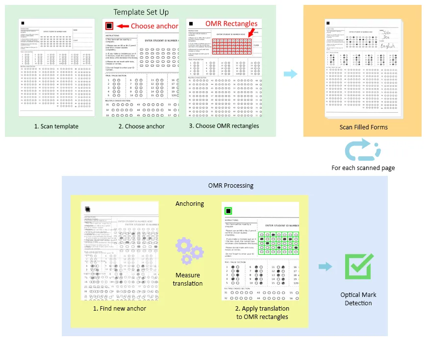
The template is usually a blank document on which you mark the location of the data to extract. That data has two parts:
- Anchor — A logo, black rectangle, or solid object at the edge of the document that repeats on every filled form.
- OMR Fields — The locations of the fields that need to be filled in. GdPicture.NET uses rectangles surrounding the fields to specify their location for the recognition algorithm.
Scanned forms
These are the same forms as the template, but with the human-marked data on them. In other words, they’re the documents we want to extract information from.
Types of OMR fields
OMR fields come in numerous types, and the most common ones follow.
A field can be a shape such as a square, a circle, or an oval.
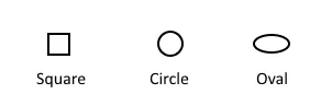
On multiple choice exams, these shapes often have characters — such as numbers or letters — inside of them.

OMR recognizes any of these shapes, as long as you specify the shape and whether it contains a character.
Problems causing bad OMR
Three known issues degrade OMR quality:
- Low DPI Images — These are images with 150 dots per inch or less. Low resolution degrades the image, and with it the OMR fields and the content inside them.
- Small Fields — If the OMR fields are too small, the decision often rests on just a few pixels. The recognition algorithm then has too little data to decide accurately, so the margin of error grows.
- Translation Due to Scanning — In a scanned filled document, the OMR fields never land exactly where the template specified:
- A scanned document never sits in exactly the same position in the scanner as the template document did.
- Stretching along both axes, caused by the feeding mechanism of the scanner’s automatic document feeder when one is used.
Form design remedies the first two problems: Scan at 200–300 DPI and make the OMR fields large enough to contain more than a few pixels. For the third problem, GdPicture.NET Library has an anchoring engine that helps measure this translation and amend your data locations.
Anchoring: Overcoming the translation problem
One part of the template form is the anchor — a logo, rectangle, or solid object. It measures the translation between the template document and the scanned filled forms.
An anchor works because it shows up on every document, whatever the sampling used, and carries enough data (black pixels) to be recognized.
Registering where the anchor landed gives a location to compare against the template.
The difference between the two locations on the X and Y axes is the translation, and it applies to the whole document.
Applying that translation to the OMR field rectangles from the template document puts them in their correct place. That gives the location of the OMR fields in the filled document.
The images below show this process, from setting up the template through to detecting optical marks.